Two case studies on Hyper Compressors
The first case is based on the hyper machine (secondary compressor), where in October 2011, during a start-up phase, the pressure on the 2nd stage was insufficient and the compressor was not able to deliver the pressure to the Tubular Reactor. The 1st stage produced the maximum pressure but the 2nd stage failed to produce the required plant pressure. As a consequence, the production process had been stopped.

The Secondary Compressor is a Traverse Hyper with a design mass flow of 160 000 kg/h and volume of 126.860 Nm³/hour by an process suction pressure of 276 bar(a) and a discharge pressure of 2651 bar(a).
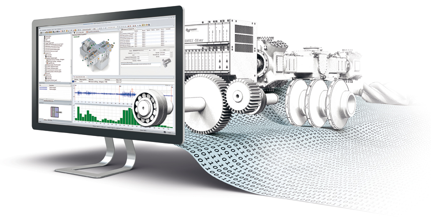
The machine has on each stage 6 single acting cylinders, so that this 2-stage Hyper has 12 compression chambers.Tasnee uses PROGNOST®-NT for condition monitoring and machine protection. With the system it is possible to continuously analyse the condition of the machine. The compressor is equipped with, besides frame vibration velocity sensors, acceleration sensors at the cylinder head and at the intermediate crosshead slide on each cylinder. The plunger displacement in x/y direction is visible as well as an orbit data set. Both are automatically analysed.
The dynamic pressure inside the compression chamber can be shown by indirect measurement (strain gauge rings).
But what happened Oct 16, 2011?
After a standard plant shut down for maintenance actions, the 1st stage had it’s maximum discharge pressure, but the 2nd stage was not able to build up the pressure. The plant had a safe shut down to open the 2nd stage cylinder 2E for confirmation of a central valve failure. The maintenance team at site decided this after the final evaluation of the pV-diagram analysis. The following picture shows the failure mode.

The findings after opening cylinder 2E
The suction valve pin was found damaged and it had moved from its actual position. Imprints of the pin were visible on the suction valve seat. This movement and the gap created between the suction valve seat had caused the gas to short circuit back to the suction side and restricted the pressure to increase.
Conclusion
The final conclusion was, that the team at site made the right decision to stop the machine shortly to re-open only the cylinder 2E. This was committed by the diagnostic work and a previously maintenance work, where this central valve was replaced as well. The pV diagram analysis was the key for this decision.
Read and watch videos with further information about the important topic of pV diagram analyses:
Performance Optimization with pV diagram analyses
How to identify failures with pV diagram analyses
How to detect valve failures with automated pV diagram analyses